Bootloader application for programming the nRF24LU1+ through the USB interface.
Introduction
The nRF24LU1+ bootloader allows you to program the nRF24LU1+ through the USB interface. The bootloader is pre-programmed into the nRF24LU1+ flash memory and automatically starts when power is applied. After start-up the bootloader copies the flash programming code to the internal SRAM from where the complete flash memory can be programmed. The bootloader occupies the topmost 2K bytes (KB) of the flash and is not deleted unless the user program extends into this area. If the program is larger than 30KB the bootloader is overwritten and lost. In addition to the topmost 2KB of the flash, the bootloader also uses the 3 byte reset vector at address 0. If your application needs to re-execute the bootloader; you must restore the reset vector so that the bootloader executes after power on reset.
Flash Layout
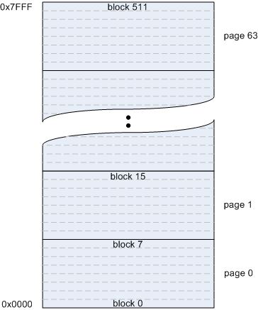
The 32KB flash is divided into 64 pages of 512 Bytes each. Since the maximum USB packet size in nRF24LU1+ is 64 bytes the bootloader divides each flash page into 8 blocks of 64 bytes each as shown in the following figure:

Relation between address, pages and blocks
USB Protocol
nRF24LU1+ begins enumerating when connected to a USB host and is available to the operating system. A driver, or application, communicating with the bootloader must use the following parameters:
| USB Specific Parameters | Value |
| VID (Vendor Identification) | 0x1915 |
| PID (Product Identification) | 0x0101 |
| Bulk In endpoint address | 0x81 |
| Bulk out endpoint address | 0x01 |
The USB host communicates with the bootloader by writing commands to the IN endpoint. All USB commands to the bootloader start with a 1-byte identifier (cmd id) and return a packet. If the command takes parameters, the parameters are written as one or two bytes after the one byte identifier, for example, command 0x02 takes the parameter pn. Each command returns a value that must be read from the OUT endpoint.
Firmware Version (cmd id 0x01)

This command returns firmware information of the bootloader. hb is the version number and lb contains other bootloader information. Currently bit 0 is used to indicate flash size: bit0=0 means 16KB flash and bit0=1 means 32KB flash.
Flash Write Init (cmd 0x02)
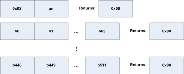
This command is sent to the bootloader to start writing a flash page to the page indicated by the parameter pn. After this command is completed the host must send the 8 blocks that constitute the page. This is done by sending 64 byte packets to the USB IN endpoint with the contents of the block. The bootloader responds with a one-byte packet (containing 0x00) after each packet has been sent.

Read Flash (cmd 0x03)
This command is sent by the host to read one of the 64-byte flash blocks. The block is indicated by the parameter bn (bits 0-7 only. Bit 8 is set by cmd 6 below). If the flash main block readback disable is effective this command returns 0x00 in all bytes in the flash page containing the block is used (programmed) and 0xff if it is empty.

Flash Page Erase (cmd 0x04)
This command is used mainly for debugging purposes since the Flash Page Write command above automatically erases the page if needed prior to programming. Using this command erases page pn.

Turn on flash main block readback disable (cmd 0x05)

This command returns 0x00 if successful or 0x01 if the bootloader failed to turn on flash main block readback disable. The device must be reset for the readback disable to be effective.
Select flash half (cmd 0x06)

This command is used to select which flash half command 0x03 works against (bit 8 of the block number). When n = 0 the lower 16KB flash is selected and when
= 1 the upper 16KB is selected. The reason for having this command is to make sure the interface and commands for the LU1 bootloader are the same on the LU1+.
 1.7.2
1.7.2