Link layer for the nRF24L01+ radio.
Contents
- Introduction
- Roles in a Gazell star network
- Properties of Gazell
- Protocol states
- Protocol timing in Gazell
- Pipes and addresses in Gazell
- Configuration
- Application Programming Interface (API) for the Gazell Link Layer
Introduction
Gazell Link Layer is a library with functions for setting up and configuring the link layer of a wireless desktop or other wireless applications. The Gazell Link Layer replaces the earlier Frequency Agility Protocol from Nordic Semiconductor. In the rest of this text we will shorten "Gazell Link Layer" to "Gazell".
Each Gazell node can be configured for communication with up to six other Gazell devices in a network. Each node can transmit and receive data. Networks with more than seven (1+6) nodes can be set up to work with Gazell, but no Gazell node in the network can know more than six other nodes.
For the sake of simplicity we will in the rest of the help file assume that we have a star network with one Host node and one to six Device nodes. With this network it is very easy to write a wireless application using Gazell, since no network layer will be needed on top of Gazell. Setting up addresses and channel tables is also very simple for a star network.
Roles in a Gazell star network
In a simple Gazell star network we have two static roles: Host and Device. There will be one Host and one to six Devices in the network. This is a typical wireless desktop configuration where no role switching is ever required - there will be a "dongle" that is always a Host, plus a mouse, keyboard and other input units that are always Devices.
A Host mainly receives data, but can still send data back to a transmitting Device by piggy-backing data onto the acknowledgement packets returned to that Device.
A Device mainly transmits data, but can still receive data in the acknowledgements returned from the Host.
It is always a Device that initiates a data transfer. This means that a Host has to wait for a packet from a Device before it can send anything to the Device. Note that it is still possible to fulfill latency requirements for Host to Device traffic (like a command from the PC to turn on the caps lock LED on a keyboard). The application on the Device side will just have to send dummy poll packets at regular intervals to the Host. The Host will then return any pending data in the following acknowledgement. In a typical desktop application the Host to Device latency requirement is usually so relaxed that such a poll will not consume significant power.
Properties of Gazell
Low Power
Gazell is a protocol designed to minimize power consumption. For applications like wireless desktops or remote controls where the power capability on Host and Device are very different, Gazell will operate in an asymmetric mode where the Devices draw much less power than the Host.
In this mode the Device is free to send data at its own discretion. A remote control will for instance only send each time a button is pressed. All "protocol smalltalk" just to maintain a link is thus avoided. This minimizes power on the Device side at the cost of more power on the Host, since the Host will have to always listen.
In battery-to-battery operations, where power saving is equally important on both Host and Device side, Gazell can be set up in a more symmetric mode where both Host and Device have a low duty cycle. In this case there is a trade-off between latency and power consumption. The longer latency one can accept, the lower the power consumption will be. This tradeoff can be configured by Gazell.
To minimize power and latency in applications with high report rates, Gazell also has a semi-synchronized mode. This mode needs an accurate system clock on both sides. This mode does not use power-wasting synchronization messages to keep Host and Device in sync. Instead the Device uses the ordinary acknowledgment packets to synchronize its transmission channel time slots with the Host whenever an ACK is received.
Note that synchronization occurs at the discretion of the Device - the Host does not even know whether the Device is synchronized or not. This means that some Devices can operate in asynchronous mode at the same time as other Devices are in synchronous mode.
Gazell does not lose any data when the Host and Device eventually drift out of sync - it merely leads to more retransmissions until the Device is able to sync up again. As soon as a retransmitted packet is acknowledged, the Device will use the arrival time of the acknowledgement to adjust its synchronization. So this is an imprecise sync mechanism where power and latency are saved whenever the protocol is in sync, but the protocol is still working fine when we happen to be out of sync. We call it "semi-synchronized mode".
Robust against interference
Gazell can be configured with frequency agility or frequency hopping to avoid interferers. "Frequency agility" means that the protocol stays on the same frequency channel as long as there is little interference on that channel. When a channel is quiet it makes little sense to switch to another channel. The new channel is more likely to have interference than the current channel, so unconditionally switching channels for each packet would increase the average number of transmissions and thus the average power consumption and latency.
"Frequency hopping" means that that the protocol changes channel for each packet transmitted. This is required by some radio regulations to spread the radio power across the spectrum when power amplifiers are used to increase the range of the radio.
Gazell itself will cause little interference for other 2.4 GHz radios since the protocol does not need to send packets to maintain a link. Gazell is only active when there is data to send. This also gives little interference between Devices talking to the same Host. (These Devices have no knowledge of each other and operate independently of each other.)
The size of the channel table is a trade-off between latency and robustness. Having a large channel table gives us the option of trying many channels from the 2.4 GHz band to find a quiet channel. But this means that the Host and Device need more time to find each other and consequently more transmissions per packet, increasing power consumption and latency.
Gazell has configurable channel tables. Experience has shown us that having three to five channels spread out in the 2.4 GHz band is a good compromise, giving very low latency and maintaining good immunity to interference.
Low latency and high report rate
The perceived responsiveness and accuracy of a Device like a wireless mouse depends on the sample rate and resolution of the optical sensor, but equally on the report rate and latency of the radio protocol.
Gazell is a simple protocol with little protocol overhead and, combined with 2 Mbits/s data rate of Nordic Semiconductor radios, we get high report rates.
Gazell achieves low latency by two means: asymmetric duty cycles and semi-synchronization. Asymmetric duty cycles means that the Host can be configured to always listen while the Device only has to send whenever there is data. Therefore the Device does not have to wait for the next listening-slot on the Host before starting a transmission attempt.
The semi-synchronized mode described earlier also helps to achieve low latency, since when we are in sync the Device will hit the correct channel and channel time-slot at the Host every time.
Simplicity
Using the Gazell protocol is easy. Since the Devices in a Gazell star network do not know about each other and there is no co-ordination between them, setting up the Devices becomes very simple.
There are no special connection setup packets - all packets are data packets - and Gazell has no need for packet headers of its own. We do not need send link packets at regular intervals to maintain a link. A Device can be turned off or removed from the network at any time, and the Device can re-enter the network at any time later.
Encryption
Gazell supports AES encryption. The encryption is transparent to the application. Secure key exchange will have to be set up by the application - pairing is not supported in the Gazell Link Layer itself.
Encryption can be set up individually for each link. For instance, a Host can run encrypted communication with a keyboard Device and at the same time communicate in clear text with a mouse Device.
Gazell uses an AES counter mode scheme for encryption. This scheme requires five bytes overhead in each data packet to keep the counter synchronized on Device and Host. Encryption will increase latency by 1-2 ms when using nRF24LE1 and 40-50 us when using nRF24LU1.
Protocol states
Gazell is either in an idle state where there is no radio activity, or in an active state in the role of either Host or Device. The Gazell Link Layer protocol state machine has three main states:
- GZLL_IDLE
- GZLL_HOST_ACTIVE
- GZLL_DEVICE_ACTIVE
In the following we for simplicity shorten these state names to:
- IDLE
- HOST
- DEVICE
IDLE state
In IDLE state the protocol neither transmits nor receives. The radio is either in STANDBY or POWER DOWN mode, as selected by the application.
Gazell starts in IDLE state after the function call gzll_init(). The application can force Gazell into IDLE state with gzll_goto_idle() at any time.
HOST state
In HOST state the protocol listens for incoming data. Gazell enters HOST state with the function call gzll_rx_start(). Received packets are stored in the radio receive (RX) FIFO. Gazell will remain in HOST state indefinitely unless a receive-timeout has been set. The application can also interrupt HOST state and return to IDLE state with the function call gzll_goto_idle().
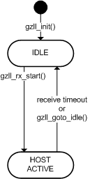
Gazell protocol states for a Host
Note that for a star network the Host should only be in the states IDLE and HOST. If a Host application calls gzll_tx_data() the Host will enter the DEVICE state and switch roles and become a Device. Then we do not have a star network any more - just a set of unconnected Devices.
Gazell supports two HOST-state modes:
- Mode 0: low latency mode
- Mode 1: low power mode
In low latency mode the Host listens continuously. Each channel in the channel table is monitored in a rotating fashion. This mode is used when the Host has ample power and when low latency for Device to Host data is important.
In low power mode the Host radio is in POWER DOWN or STANDBY between listening periods. In each listening period, the Host listens for a short time on one channel. Then the Host goes to sleep for a while before listening on the next channel. This gives less power consumption on the Host side than for low latency mode.
In asynchronous mode (see below) a Host in low power mode means more transmission attempts and thereby longer latencies and more power consumption on the Device side. However, in semi-synchronous mode the Device will be synchronized to the short listening periods of the Host, so we do not waste transmit attempts and power at the Device side. (But we will still get increased latency.)
Low power mode is used for battery-powered Hosts and when a Host is in standby mode. It is normal for a Host to switch between the low power mode and low latency mode. A Host like a USB-dongle for a wireless mouse will for instance be in low latency mode when the mouse and PC are active, but will switch to low power mode when the PC is inactive and the USB-dongle enters SUSPEND mode.
DEVICE state
In DEVICE state, the protocol sends data. Gazell enters DEVICE state with the function call gzll_tx_data(). Gazell handles re-transmission of lost packets and channel changes to avoid interference. This is transparent to the application.
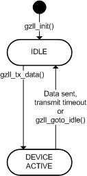
Gazell protocol states for a Device
Gazell will continue to transmit as long as there is data in the transmit FIFO. A transmit timeout can be set that interrupts transmission which is not successful within a given time. The application can also interrupt DEVICE state and return to IDLE state with the function call gzll_goto_idle().
Note that for a star network, a Device should only be in the states IDLE and DEVICE. If a Device application calls gzll_rx_start() the Device will enter the HOST state and switch role and become a Host. We then have a network with two Hosts, which is not a star network any more.
In DEVICE state a Device will continue to transmit as long as there are pending packets in the TX FIFO of the radio. New packets can be uploaded to the TX FIFO during transmission.
A timeout period can be set. This will limit the time for retransmission of a packet. If a packet has not been acknowledged within the timeout period, the protocol will give up and return to IDLE state. The application will then have to consider what to do with the packet that failed to be transmitted and with the other packets in the TX FIFO of the radio.
Gazell supports five modes of transmit operation in the DEVICE state. These five modes are grouped into two categories:
- Semi-synchronous operation mode
- Asynchronous operation mode
Semi-synchronous mode
In semi-synchronous mode the Device will try to synchronize its transmission time slot with the Host's listening time slot for the channel to be used. The Host rotates quickly through the channel table, listening for a while on each channel. The Device will also go through all channels in the channel table, re-transmitting the packet on a given channels for a full rotation at the Host, until "hitting" both channel and time slot on the Host. The Device will then use the arrival time of the acknowledgment packet returned from the Host to "calibrate" its synchronization timer. Note that the Host is ignorant of the Device's attempts to synchronize with the Host.
When synchronization is successful, the Device can then always send a packet on the right channel within the listening slot for that channel on the Host. This will minimize the number of transmissions of each packet - when there is no interference each packet will be sent only once.
The Device can know that sync has been achieved when the number of retransmissions gets close to zero. The function gzll_get_tx_attempts() returns the number of transmit attempts for the current packet. (When there is heavy radio interference, the Device will have difficulty achieving sync, since it cannot know whether a missing ACK is caused by external interference or by itself being out of sync.)
Note that a semi-synchronized Device is free to select any channel for its next transmission. It knows in which time slots the Host is monitoring a particular channel and merely waits until that time slot comes up before transmitting.
If synchronization is unsuccessful for a while due to clock drift or radio interference, the protocol will still work. Gazell will just operate as in asynchronous mode until the next acknowledgment is received and the sync timer can be adjusted again.
Asynchronous mode
Semi-synchronization saves transmissions and thus radio power but causes a small penalty on microcontroller power: we need to run an accurate synchronization timer between each transmission. When a Device only sends a little data now and then, it is unlikely that the Device can achieve synchronization with its Host. Then it is not worthwhile to spend power on running an accurate clock, and we are better off running Gazell in asynchronous mode.
In asynchronous mode, Gazell must perform a kind of Device discovery for each packet sent. This costs some extra transmissions, but the advantage is that the Device can be in power down between transmissions for as long time as it wants. A simple remote control Device will typically always run in asynchronous mode.
Frequency hopping in Gazell
In Gazell, the frequency hopping as seen on the air is completely determined by the Devices. The Host will for any frequency hopping policy on a Device still listen on all channels in turn, rotating through the complete channel table. The Host is configured in the same way for all Device modes, and does not even know a Device's synchronization mode or hopping policy.
A Device can select which channels to use and how often to use them. Different Devices can choose different channel hopping policies if wanted. The available channel selection policies are different for the asynchronous and semi-synchronous modes:
Channel selection policies in asynchronous mode
A Gazell Device in asynchronous mode can be set up with two channel selection policies:
- Frequency agility (FA)
- Frequency hopping spread spectrum (FHSS)
For the "frequency agility" policy, we first try the previous successful channel, assuming that this channel is still good. This is the channel that was used by the last acknowledged packet. We will stay on this channel as long as it is good. In a quiet environment we will then very seldoml change channel. If we do not succeed transmitting on the previous good channel, a pseudo-random channel is selected from the channel table.
For the "frequency hopping" policy we select a new pseudo-random channel from the channel table each time. This gives us frequency hopping spread spectrum behavior. The transmitted radio power is then spread evenly among all channels in the channel table. This behavior is required by some radio regulations when transmitting at high power, as when using a power amplifier. If we do not succeed on the first random channel, a new pseudo-random channel is selected from the channel table.
Channel selection policies in semi-synchronous mode
A Gazell Device in semi-synchronous mode can be set up with three channel selection policies:
- Frequency agility (FA)
- Frequency hopping spread spectrum (FHSS)
- Low latency frequency hopping spread spectrum (smart FHSS)
For the first two policies the selection of the first channel to try is the same as in asynchronous mode. The difference lies in how the secondary channel choice is made.
In asynchronous mode, if the first channel choice in FA or FHSS mode fails, a pseudo-random channel will be tried. In synchronous mode, if the first channel choice in FA or FHSS mode fails, the estimated Host channel will be used instead. We have sync, so the Device knows the channel rotation at the Host, and just waits until the time slot for this channel comes up a the Host, before attempting to transmit. Details of Device channel selection and transmit operation are shown in the figure below.
The third policy - low latency frequency hopping, or smart FHSS - is only meaningful for a synchronized Device. With this policy the Device immediately starts transmitting at the channel that the Host is listening on. If the Device is still in sync with the Host, we will hit the correct timer the first time, reducing latency and saving power.
Which channel that the Host is listening on at the time the application in the Device signals a start of a new transmission with gzll_tx_data(), is quite random with respect to the channel rotation at the Host. Across time we will therefore also get random spread spectrum behavior with smart FHSS. But we avoid the extra latency of the simple FHSS - the latency due to having to wait for the right time slot to come up at the Host.
To summarize, there are altogether five operation modes in the DEVICE state:
- Mode 0: asynchronous mode, frequency agility
- Mode 1: asynchronous mode, frequency hopping spread spectrum
- Mode 2: semi-synchronous mode, frequency agility
- Mode 3: semi-synchronous mode, frequency hopping spread spectrum
- Mode 4: semi-synchronous mode, low latency frequency hopping spread spectrum
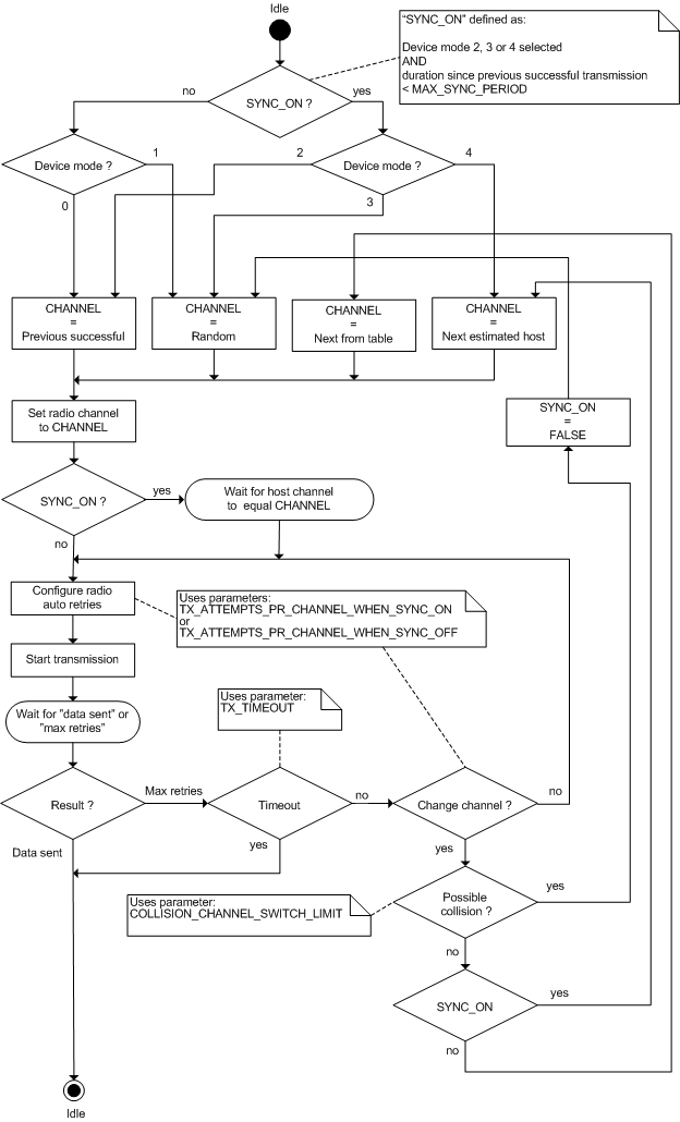
Device channel selection and transmit algorithm
Protocol timing in Gazell
For the Host there are two different channel rotation and timing schemes, depending on receive mode. In low latency mode the Host is always listening, rotating through its channel table. In low power mode, the Host is only listening intermittently, "sleeping" in between. The Device can in both cases decide to try to synchronize to the Host, or can choose to run asynchronously. The timing in the two cases are as follows:
Low latency mode
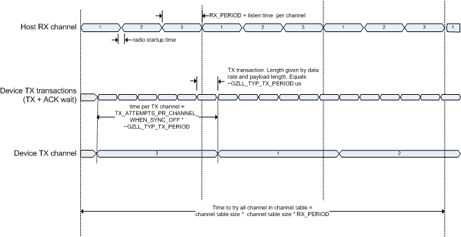
Asynchronous operation: Host in low latency mode, Device in transmit mode 0 or 1
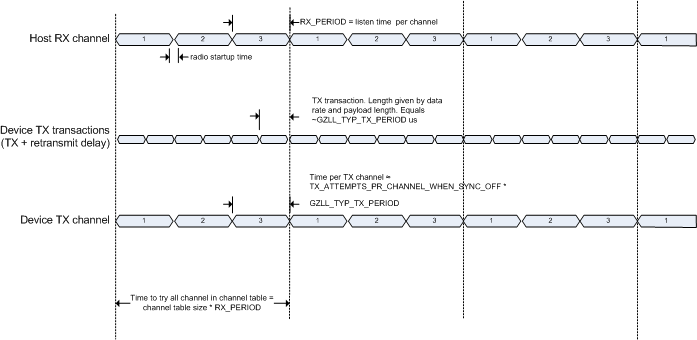
Semi-synchronous operation: Host in low latency mode, Device in transmit mode 2, 3 or 4
Low power mode
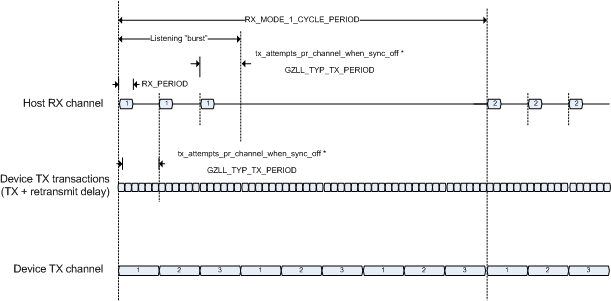
Asynchronous operation: Host in low power mode, Device in transmit mode 0 or 1
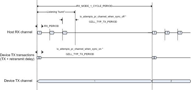
Semi-synchronous operation: Host in low power mode, Device in transmit mode 2, 3 or 4
Pipes and addresses in Gazell
In Gazell a Host or Device can be set up with up to six bi-directional pipes. Each pipe has its own address used for both receiving and transmitting. This is a more general pipe concept than the hardware pipes of the nRF24xx radios.
In an nRF24xx radio the hardware pipes are for incoming data only. There are six hardware pipes for incoming data, each with its own address. However the radio only has a single address for transmission (except for acknowledgment packets).
The more general pipes and addressing in Gazell makes it possible to build more general networks. The mapping from the general adressing and bidirectional pipes used in Gazell to the more constrained pipes of the underlying hardware is transparent to the application.
Configuration
The Gazell protocol can be customized for a range of different applications. The protocol behavior is defined by setting static and dynamic parameters.
Dynamic parameters
Dynamic parameters can be modified during runtime by the application. Dynamic parameters are accessed using the functions gzll_set_param(), gzll_get_param() and gzll_get_param_max(). Gazell addresses and channels are set with gzll_set_address() and gzll_set_channels(). Default values for the dynamic parameters are defined in gzll_parameters.h.
Note that to set a dynamic parameter denoted SOMETHING in the text below, the function call will be: gzll_set_param(GZLL_PARAM_SOMETHING, some_value). We use the shorter form here just to make the text more readable.
DEVICE_MODE
DEVICE_MODE defines the transmit mode of a Device. Gazell has five different transmit modes. See
Protocol states
TX_TIMEOUT
TX_TIMEOUT defines the total number of failed transmit attempts before Gazell returns to IDLE state. An infinite timeout can be specified by setting TX_TIMEOUT to 0.
The exact duration of a single transmit attempt depends on data rate and packet size. The parameter GZLL_TYP_TX_PERIOD is the approximate duration of a single transmit attempt in microseconds.
TX_ATTEMPTS_PR_CHANNEL_WHEN_SYNC_ON
TX_ATTEMPTS_PR_CHANNEL_WHEN_SYNC_ON defines the number of transmit attempts on one channel before switching to another channel, when synchronization is on.
This parameter should be set so that the total transmit time on one channel is less than the receive period specified by RX_PERIOD.
In semi-synchronous operation, a Device will always start to transmit on the same channel as the Host listens on, and it is only useful to continue transmitting on this channel as long as the Host is receiving on this channel.
A typical value for TX_ATTEMPTS_PR_CHANNEL_WHEN_SYNC_ON is therefore (RX_PERIOD / GZLL_TYP_TX_PERIOD).
TX_ATTEMPTS_PR_CHANNEL_WHEN_SYNC_OFF
TX_ATTEMPTS_PR_CHANNEL_WHEN_SYNC_OFF defines the number of transmit attempts on one channel before switching to another channel, when synchronization is off.
In asynchronous operation, a Device will start to transmit on a random channel relative to the Host's receive channel rotation. To ensure that the transmit channel on the Device and the receive channel on the Host coincide at least once before changing channel, this parameter should be selected so that a single transmit frequency is used throughout a full channel rotation on the receiver.
TX_ATTEMPTS_PR_CHANNEL_WHEN_SYNC_OFF should therefore be larger than ((RX_PERIOD * channel subset size) / GZLL_TYP_TX_PERIOD.).
HOST_MODE
RX_MODE defines the receive mode of a Host. RX_MODE = 0 selects low latency operation while RX_MODE = 1 selects low power operation.
Note that RX_MODE also has to be set on the Device - to the same value as on the Host - since a Device must know the Host's receive mode to be able to obtain synchronization.
RX_PIPES
RX_PIPES defines which pipes to listen to. The 6 least significant bits of RX_PIPES is used to enable and disable pipes. Bit 0 = 1 enables pipe 0, bit 1 = 1 enables pipe 1 and so on.
CRYPT_PIPES
CRYPT_PIPES defines which pipes should be encrypted. Bit 0 = 1 enables encryption on pipe 0, bit 1 = 1 enables encryption on pipe 1 and so on.
To enable encryption GZLL_ENABLE_CRYPT must also be defined.
RX_TIMEOUT
RX_TIMEOUT defines the number of RX_PERIODs a host will listen before automatically returning to IDLE state. RX_PERIOD is given in microseconds, so the timeout will equal RX_TIMEOUT * RX_PERIOD microseconds.
An infinite timeout can be specified by setting RX_TIMEOUT to 0.
RX_PERIOD
RX_PERIOD defines the listening time per channel on the Host. RX_PERIOD is given in microseconds. RX_PERIOD should be >= GZLL_TYP_TX_PERIOD to ensure that a Device continuously transmitting on a single channel will "hit" the Host at least once.
RX_PERIOD_MODIFIER
RX_PERIOD_MODIFIER is used by a Device for "calibrating" its synchronization timer.
Whenever a packet is successfully transmitted by a Device (acknowledgment returned from Host), the protocol timer on the Device is adjusted so that the next timer interrupt on the Device occurs RX_PERIOD microseconds after the estimated time the packet was sent from the Host. This will make the next packet from the Device "hit" the Host at the same time relative to the listening slot at the Host as the previous packet.
A good value for RX_PERIOD_MODIFIER is most easily found empirically. A good value has been found when the number of retransmissions in semi-synchronous mode gets close to zero. If the average number of transmission attempts per packet equals zero, the parameter value closest to optimal has most likely been found. However, it is actually recommended to select a value giving an average number of retransmission as close as possible to zero but not equal to zero. This is to ensure that if the device eventually comes out of synchronization with the host, it will only need a single re-transmit attempt to re-establish synchronization, instead of having to transmit throughout an entire rotation of the channel subset at the host.
Typically a suitable value is in the range 350 - 450.
RX_CHANNEL_HOLD_PERIODS
RX_CHANNEL_HOLD_PERIODS defines the number of Host receive time slots (RX_PERIODs) that the Host shall remain on the same channel when a packet is received. This can be used to enable a streaming type of operation where a burst of packets from a Device can be sent on the same channel, avoiding channel switching. (It takes time for the radio to change channel.)
OUTPUT_POWER
OUTPUT_POWER defines the radio output power. Possible values are:
- HAL_NRF_0DBM for 0 dBm output power
- HAL_NRF_6DBM for -6 dBm output power
- HAL_NRF_12DBM for -12 dBm output power
- HAL_NRF_18DBM for -18 dBm output power
POWER_DOWN_IDLE_ENABLE
When POWER_DOWN_IDLE_ENABLE is non-zero, the radio will go to POWER DOWN in IDLE state, otherwise the radio will go to STANDBY.
In STANDBY the radio consumes more power than in POWER DOWN, but the radio start-up time is shorter, which will result in a lower transmit latency when starting a new transmit operation.
MAX_SYNC_PERIOD
MAX_SYNC_PERIOD defines how long a Device will consider itself "in sync" (SYNC_ON) after a successful (acknowledged) transmission.
For each acknowledged transmission a Device will synchronize to the Host. After some time without activity the Device will eventually drift out of synchronization. After MAX_SYNC_PERIOD Gazell will assume that sync has been lost.
HOST_MODE_1_CYCLE_PERIOD
RX_MODE_1_CYCLE_PERIOD defines the duration of the low power cycle on a Host in low power receive mode. A long period will give low power consumption but increased latency.
The parameter is specified in number of RX_PERIODs. The cycle period will equal RX_MODE_1_CYCLE_PERIOD * RX_PERIOD microseconds.
COLLISION_CHANNEL_SWITCH_LIMIT
COLLISION_CHANNEL_SWITCH_LIMIT defines the maximum number of channel switches in semi-synchronous mode.
If several Devices operating in semi-synchronous mode are talking to the same Host, there is a risk that these Devices sooner or later will start transmitting synchronously at the same channels, and thus collide on every transmission attempt.
A large number of channel switches may indicate that this has occurred. If the number of channel switches exceeds COLLISION_CHANNEL_SWITCH_LIMIT, a Device will temporarily exit semi-synchronous mode and start selecting random channels in order to escape this unintended synchronization.
Static parameters
The static parameters have to be defined prior to compilation and cannot be altered during runtime. These parameters are also defined in gzll_parameters.h. All static parameters are named GZLL_...
GZLL_DATARATE
GZLL_DATARATE defines the radio data rate. Possible values are:
- GZLL_DR_2MPS
- GZLL_DR_1MPS
- GZLL_DR_250KBPS
In general, a high data rate will lead to low power consumption as the transmission time will be reduced. In addition the coexistence performance is normally improved since shorter time on air reduces the risk of collisions. A low data rate increases the receiver sensitivity, which will increase the maximum range of the radio link.
GZLL_MAX_CHANNEL_TAB_SIZE
GZLL_MAX_CHANNEL_TAB_SIZE defines the maximum channel table size allowed.
GZLL_MAX_FW_PAYLOAD_LENGTH
GZLL_MAX_FW_PAYLOAD_LENGTH defines the maximum payload length for a Device to Host packet (that is, a packet in "forward" direction). The maximum value that can be set for GZLL_MAX_FW_PAYLOAD_LENGTH is 32 bytes without encryption and 27 byte with encryption. (AES in counter mode as used by Gazell incurs a packet overhead of 5 bytes.)
GZLL_MAX_ACK_PAYLOAD_LENGTH
GZLL_MAX_ACK_PAYLOAD_LENGTH defines the maximum payload length for a Host to Device acknowledgment packet. This parameter is also used to compute the auto retransmit delay. A long ACK payload length will require a longer retransmit delay between each transmission attempt from a Device.
GZLL_CRYPT_ENABLE
GZLL_CRYPT_ENABLE must be defined in order to use encryption at all.
GZLL_MAX_CRYPT_PIPES
GZLL_MAX_CRYPT_PIPES defines the maximum number of pipes that will be able to use AES encryption. The pipes that will be able to use encryption is given as (0 <= pipe < GZLL_MAX_CRYPT_PIPES).
For example, if GZLL_MAX_CRYPT_PIPES is set to 3, pipe 0, 1 and 2 may use encryption.
GZLL_HOST_ONLY
GZLL_HOST_ONLY may be defined to disable all Device functions in order to minimize code size.
GZLL_DEVICE_ONLY
GZLL_DEVICE_ONLY may be defined to disable all Host functions in order to minimize code size.
 1.7.2
1.7.2